Weld quality depends on more than selecting a stainless-steel electrode: an incorrect grade match, embedded carbon-steel particles, excess heat or an oxidised root can undermine strength and corrosion resistance. By the end, you will be able to verify the base metal, choose a compatible filler, control heat and shielding, prepare the joint correctly and define checks that reveal hidden defects.
Key takeaways
- Confirm the stainless grade with PMI before selecting filler metal.
- Keep tools, surfaces and consumables free from carbon-steel contamination.
- Control heat input, fit-up and welding sequence to reduce distortion.
- Verify weld appearance, defects, purge quality and consumable traceability.
Confirm the Stainless Grade Before Choosing Filler Metal
Do not choose a rod from colour or a “stainless steel” label. Check the material test certificate, heat number and mill marking, then confirm the base-metal identification with positive material identification (PMI). X-ray fluorescence identifies chromium, nickel and molybdenum; optical emission spectroscopy is needed when carbon content separates 304L from 304 or 316L from 316.
| Base metal | Usual filler classification | When it applies |
|---|---|---|
| 304 and 304L | 308L | Standard austenitic stainless joints where matching chromium and nickel chemistry is suitable |
| 316 and 316L | 316L filler metal classification | Joints requiring molybdenum-bearing weld metal for improved pitting resistance |
| Austenitic stainless to carbon steel | 309L dissimilar joints | The higher chromium and nickel content tolerates dilution from the carbon-steel side |
| Duplex 2205 | 2209 consumable | Duplex weld chemistry requires a balanced ferrite-austenite structure |
| Heat-resistant 25Cr-20Ni stainless | E310 | High-temperature service, not routine joining of 304 or 316 |
| 904L or similar high-alloy stainless | ER385 | High molybdenum and nickel requirements confirmed by the procedure |
Low-carbon 308L and 316L consumables reduce chromium-carbide sensitisation during prolonged exposure to approximately 425–850 °C. Do not substitute E310, ER385 or nickel alloys because their names sound more corrosion-resistant; their chemistry can be wrong for dilution, phase balance or service temperature. Verify the filler classification, lot identity and storage condition before opening the package.
Prepare Surfaces and Consumables Without Introducing Contamination
Oil and chloride residue can become corrosion sites after welding, so clean the joint before any arc starts. Use a solvent approved for stainless steel when degreasing stainless steel; exclude chloride cleaners, bleach and chlorinated solvents. Wipe with lint-free cloths and allow the surface to dry.
1. Remove oxide, burrs and embedded dirt with a stainless-steel wire brush and a dedicated grinding wheel reserved for stainless steel. Carbon-steel contamination from shared brushes, wheels or grinding dust can leave iron particles that later rust-stain the weld or trigger local corrosion.
2. Keep the joint, backing, tools and consumables free from moisture. Water in a root gap or on filler promotes porosity and hydrogen-related defects, while damp packaging signals a storage failure.
3. Control electrode storage in the original, sealed, identification-controlled packaging. Keep opened low-hydrogen electrodes at the manufacturer’s specified holding temperature, and rebake them only to the stated schedule. Reject filler with rust, oil, damaged coating, bent wire, wet packaging or uncertain filler identification.
4. Remove heavy heat tint after welding with the specified mechanical treatment, pickling or electropolishing process, then rinse thoroughly with clean water. Brushing away visible colour alone does not restore the passive surface. Use ferroxyl testing when you need evidence that free iron remains absent, especially on corrosion-critical fabrications.
Record the cleaning method and consumable lot with the weld documentation. A clean appearance is not proof of corrosion readiness; inspect crevices, weld spatter and the heat-affected zone before release.
Control Heat Input, Fit-Up and Welding Sequence
Do not chase penetration by increasing amperage alone. Stainless steel’s low thermal conductivity and high expansion make excess heat a fast route to distortion, wide heat-affected zones and corrosion loss. Control heat input through amperage, travel speed and bead size, then follow the qualified WPS.
1. Measure joint fit-up before striking the arc. Set the specified root gap, align the faces, and use close, evenly distributed tack spacing. Excessive gap encourages a large root bead; a tight gap can cause incomplete fusion. Minimise joint restraint because rigid fixtures transfer shrinkage into residual stress and distortion.
2. Use short weld runs and a balanced welding sequence. Alternate sides or segments where the joint permits, and allow each run to cool before placing the next. Smaller beads reduce distortion and repeated reheating, while excessive travel speed can leave incomplete fusion even at correct amperage.
3. Keep the interpass temperature within the WPS limit. For austenitic grades, a 150 °C interpass limit is a common control value; prolonged heating in the 425–850 °C sensitisation range can cause chromium-carbide precipitation and intergranular corrosion. Low-carbon filler does not remove the need for temperature control.
4. Treat duplex separately: duplex 100–150 °C limits and the qualified heat-input window control ferrite-austenite balance, cooling rate and phase precipitation. The WPS takes precedence over generic limits. Record amperage, voltage, travel speed and interpass readings so heat input and distortion remain traceable.
Set Current, Shielding and Purging for the Welding Position
Set current from electrode diameter, welding position and process: 2.5 mm electrode amperage often starts at 50–80 A, while 3.15 mm electrode amperage often starts at 80–110 A. Use the qualified WPS first; select the lower end for vertical welding and overhead welding to control the pool and prevent sagging.
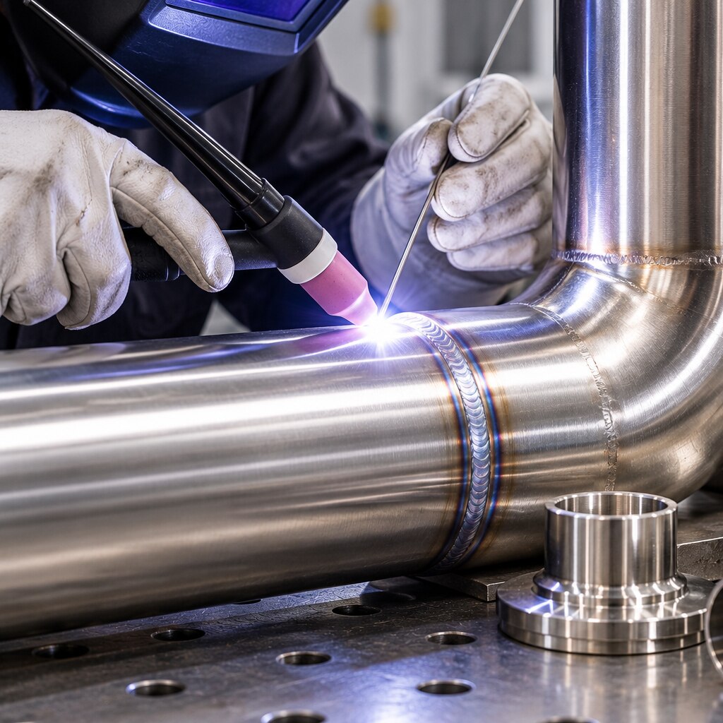
1. For TIG, also called GTAW, use high-purity argon at a gas flow rate of about 7–12 L/min. Add helium when the joint needs greater heat input or penetration, but correct turbulence before increasing flow.
Keep the torch angle about 10–15° from vertical, hold a short arc length, and stop if tungsten contamination causes an unstable arc or inclusions; regrind a contacted tungsten longitudinally or replace it.
2. For GMAW, set voltage, wire-feed speed and flow together rather than raising current alone. Argon-based gas supports a stable arc; oxygen and carbon dioxide additions can improve transfer, but excessive additions oxidise the surface and reduce corrosion-ready appearance. Match the gas blend to the qualified procedure.
3. For a stainless root, use back-purging with purge dams placed close to the joint without exposing them to welding heat. Leak-test the enclosure, vent displaced air, and wait for the target before striking the arc: oxygen below 1,000 ppm suits general work, while critical austenitic or duplex work may require oxygen below 100 ppm.
A dark, sugared root proves inadequate protection.
Verify the Finished Weld and Document the Consumable Decision
Start with visual inspection of the weld profile, bead continuity, undercut, overlap, cracks, arc strikes, spatter and heat tint. Inspect the root for incomplete penetration, root oxidation and sugaring; a clean-looking cap does not prove that the concealed side is corrosion-ready.
| Inspection | Evidence to record | Limitation |
|---|---|---|
| Visual inspection | Weld profile, surface contamination and dimensions against the WPS | Cannot prove internal soundness or corrosion performance |
| Dye penetrant testing | Surface-breaking cracks and porosity after cleaning | Does not detect subsurface defects |
| Borescope examination | Root fusion, purge damage and internal sugaring in pipes or restricted joints | Requires access and adequate lighting |
| Ferrite number | Calibrated readings using AWS A4.2 or ISO 8249 | A generic magnetic reading is not a qualified substitute |
| Duplex ferrite measurement | Controlled method, surface condition, location and readings from weld metal, fusion boundary and heat-affected zone | One surface reading cannot represent the whole joint |
| Metallography and corrosion testing | Phase balance, microstructure and resistance demonstrated during qualification | Usually belongs in the PQR or a specified test plan |
For duplex welds, compare the measured ferrite range with the qualified WPS and PQR, not an isolated target. Record the filler classification, manufacturer, batch number, diameter, lot certificate, welder, joint number, heat input and inspection results; this creates traceability from finished weld to procedure and filler lot.
RND Welding Pvt Ltd can help match stainless-steel welding consumables to the required classification while preserving that documentation trail.
- Reject or investigate welds with cracking, trapped contamination, excessive heat tint, failed penetrant indications or readings outside the qualified range.
- File cleaning records and any ferroxyl examination or corrosion testing with the weld dossier.
Related products
 | Stainless Steel Welding Electrodes Esab 308L Plus Stainless Steel Welding Electrodes ₹ 450/KgGet Latest Price Product Brochure Material Stainless Steel Length 350 mm Size 2.5 mm Brand ESAB Model Name/Number 308L Plus Elongation 45 %... View product → |
 | Stainless Steel Welding Electrodes ₹ 1,700/KgGet Latest Price Diameter 2.5 mm X 450 mm Material Stainless Steel Brand Bohler Size 2.5 mm Length 350 mm Application/Usage Construction We... View product → |
Frequently asked questions
How do you confirm stainless steel grade before choosing filler metal?
Check the material test certificate, heat number and mill marking, then use PMI. X-ray fluorescence identifies chromium, nickel and molybdenum; optical emission spectroscopy separates grades by carbon content, including 304 from 304L and 316 from 316L.
How can you prevent contamination when preparing stainless steel for welding?
Clean the joint and keep stainless-only brushes, grinding wheels and tools away from carbon steel. Protect filler metals from moisture, dirt and mixed storage, and remove oil, paint, oxide and other residues before welding.
Which welding variables help maintain stainless steel weld quality?
Control heat input, joint fit-up and welding sequence to limit distortion, overheating and unwanted metallurgical changes. Set current and travel conditions for the process, thickness and welding position.
Why are shielding gas and purging important for stainless steel welding?
Correct shielding protects the arc and weld pool from atmospheric contamination. Purging the reverse side of pipe and full-penetration joints protects the root from oxidation, including dark oxide that can reduce corrosion resistance.
Related products
 | Stainless Steel Welding Electrodes ₹ 3,800/KgGet Latest Price Length 350 mm Material Stainless Steel Operating Current AC/DC Brand Arocos Size 3.15 mm Application/Usage Construction We... View product → |
 | Welding Electrodes ₹ 3,000/KgGet Latest Price Length 350/450mm Model Name/Number Different Grades avaiable Brand ADOR Material Mild Steel Electrode Diameter... View product → |
 | Stainless Steel Welding Electrodes Mangalam E308L-16 Stainless Steel Welding Electrodes ₹ 330/KgGet Latest Price Size 3.15 mm Material Stainless Steel Length 350 mm Brand Mangalam Model Name/Number E308L-16 Packaging Type Box Material... View product → |
 | Stainless Steel Welding Electrodes ₹ 130/KgGet Latest Price Size/Diameter 2.5 mm Material Mild Steel Brand Ador Size 2.5 mm Length 350 mm Application/Usage Construction We are leading... View product → |